Perhaps 555 timer is the most versatile chip ever introduced during the 70’s and still being used by many due to its inherently innumerable uses such as LED flashers for toys, battery regulators for cars, precision timing device for instrumentations and the list goes on. Not to mention its dirt cheap price and one of the most ubiquitous IC on earth.
Most hobbyist are already familiar how to bias this chip to function as either astable, monostable, FM or PWM. But recently, I’ve tried to figure out how I can use this chip to function as class d amp source that can drive a headphone good enough to play music (or a class D preamp source).
Enter Ltspice switch cad IV, whom I rely heavily in investigating the behavioral model of 555 timer which is pretty much identical to its real world brother. I started from a basic circuit configuration of a monostable multivibrator being triggered by astable one in order to establish constant frequency. Several discrete parts were added tuned to chosen frequency of operation and quiescent output state as well.
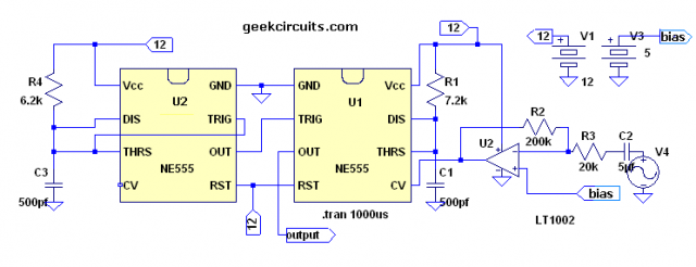
A good schematic is worth more than a thousand words. So here is the simplified schematic that can be easily understood by a newbie as shown in figure 1.
For a beginning student who hasn’t used Ltspice before, you can download it now or you will miss the trip to enjoyment. Honestly.
My initial attempt was a typical circuit configuration using R1 to charge capacitor C1 for sawtooth generation as shown from the circuit of fig.1. The 277khz clock frequency is generated by U2 at approx 98% wired as astable oscillator while U1 is wired as monostable or one shot. PWM is produced at pin 3 by modulating an audio signal at pin 5 of U1. Of course Ltspice always behaves precisely as expected. By zooming in and out of the waveforms I noticed that there are some unwanted artifacts on the waves that I’m suspecting that the source of this culprit is the coupling capacitor C2. When I removed the capacitor and retain the offset voltage of 4V on pin 5 the problem disappear.
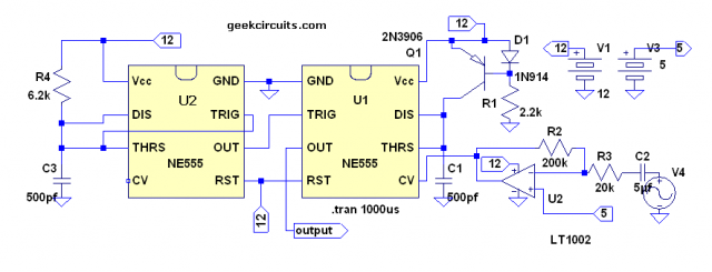
 Fig. 2 Opamp added without coupling capacitor
Another thing that’s not good is the curved voltage across capacitor C1. This is shown in fig.3.
Most professional hobbyist usually stays away from this curved sawtooth because it creates distortion so I replaced R1 with 2N3906 biased as constant current source and so; before you can see it…
Now you don’t!
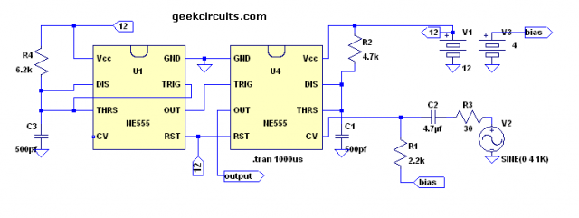
 Figure 5 the improved version of fig.1
Then I immediately grab my breadboard and 555 timer + other parts for verification in real world, (while I’m holding my breath). Lo and behold! I hope it’s not a placebo effect I’m hearing with my two ears.
While my ear cannot distinguish THD precisely, and since I am an ordinary geek guy who usually loves my own discovery, for me the sound is good enough (as usual). Of course there is always room for improvement. Several things to consider in improving the robustness of this chip for audio apps is notably to use voltage regulator for Vcc. Because if small changes occur from the supply voltage, the PWM output is severely affected as well. There’s no negative feedback from input to output; So NFB must be added to improve the overall response.
Did you notice that there’s no coupling capacitor tied to the output of opamp? This is because 4 to 5 volts DC bias to pin 5 is essential to force the upper comparator to sit at 50% of the entire dynamic charge and discharge of capacitor C1. If you attempt to put coupling capacitor there, the carrier frequency will drop to almost half. This is because C1 at pin 6 is being mirrored thru input pin 5 (or vice versa) exactly identical to conventional comparators.
I’m trying to repair my old CRT scope to capture the real word waveforms but I don’t have any luck in procuring 2.5Kv .01uf filter capacitor that leaked on its power supply a week ago. So I ended up like a cameraless paparachi.
So stick around and I’ll be back soon. Thanks for visiting my site.
Edit: BTW, I include the spice simulated file for you to play with. Just unzip it and open it inside your Ltspice switchcad. You can post a comment for what you’ve noticed or to be added to improve its usability. Good IQ exercise heh?
Simulation below:
[smartcounter:1]
Regards
IQspice-4


