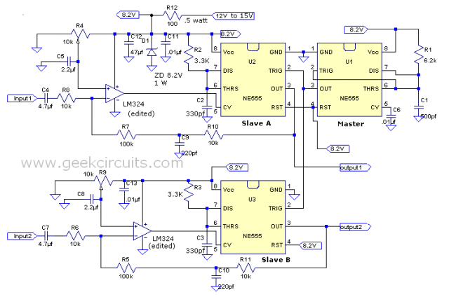
Perhaps some of you have already seen my blog in DIY audio forum showing practical use of 555 timer as class d amp source. Indeed, the circuit is quite an interesting subject to exploit specially to some curious folks looking for cheap but good sound class d audio amp project. The same circuit is shown in figure 1.
Figure 1
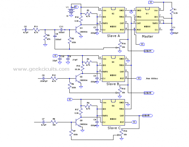
You might notice that there are numerous possible circuit configurations that may be used in producing good quality class d audio amp using this chip. Like for example to use normal opamp instead of 2N3904 as the pre amp. Figure 2 shows how it is implemented.
Figure 2
This circuit basically functions the same way as in figure 1 but use opamp as the pre amp for driving pin 5. Direct coupling is necessary to fulfill the required bias voltage of ½ VCC on pin 5. Fine adjustment to 50% duty cycle is done via R4 and R9.
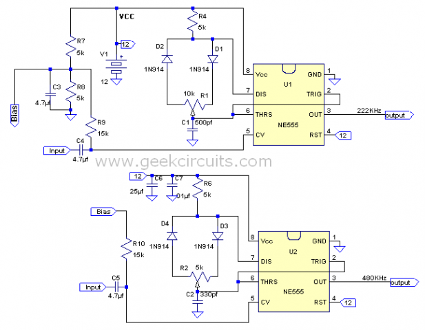
Some folks may want to try without master sync oscillator, so another possible approach is to configure all channels wired in “astable mode”. The frequency determining networks are pot R1, R2 and capacitors connected to their pin 6 and 2 respectively. The capacitor is being charged from VCC via R4 thru D1 and the pot then discharged via D2 from pot by pin 7 to obtain near square wave output as required.
Figure 3
The circuit shown above is a “preliminary audio sound test” circuit that will give some folks the taste of 555 timer as class d audio amp that can drive your stock 32 ohm MP3 headphones. If the sound excites your enthusiasm, then you may exploit it by using different approach that will fit your taste. Of course final circuit will require pre amp to match the required input voltage of the 555 timer and to facilitate the inclusion of negative FB. This is the simplest approach and is good in giving a sound quality “different” to figure 1.
This circuit utilized two pots for more precise offset null adjust at the output. Pin 5 have internal bias of 2/3 VCC equal to 8V, giving near 50% duty cycle when the pot is at the center. The thing is when pin 5 is terminated with an audio source having normal ½ VCC output, the duty cycle drops to 40%. These can be easily corrected by tweaking pot R1, R2 to get back to 50%. Please take note that direct capacitive coupling should not be use here because the output audio source itself will be the one to give pin 5 the correct bias of ½ VCC to pin 5. Of course if you insist to use coupling capacitor for audio testing purposes, then you need voltage dividing network like the one already shown in figure 3. The only caveat here is that the input sensitivity is +/- 5 volts to get full dynamic swing at the output.
Although no negative FB was implemented here, the sound is still surprisingly good. I noticed that even the audio source I used is my Acer aspire one netbook at mid volume setting, the audio sound output is still loud and good enough for my audio testing needs. The voltage dividing network R7, R8, R9, R10 along with C3 can be omitted if direct coupled audio source is implemented and that the source is ½ VCC. In any case you can adjust to 50% duty via pot R1 and R2.
The purpose of assigning more than 200 KHz channel spacing is that even their RC timing network are ideally matched, they still tend to drift in oscillation giving audible beat frequency to occur if they are oscillating at same clock frequency. Not only that, this suggested 200 KHz 400KHz channel spacing is essential for the reason I will discuss below.
Some folks may ask why 200 KHz 400 KHz channel spacing? Here is the answer;
Figure 4. Waveform without modulation
Figure 5. Upper channel circuit being modulated by +/- 1volt at 1 KHZ.
Figure 6. Waveform with 5 volts modulation at 1 KHz.
It is quite noticeable that by modulating pin 5 by +/- 1 volt at 1KHz, its oscillating frequency modulates to +/-26 KHz and when I increased the input voltage to +/- 5 volts, the frequency modulation becomes staggering. The frequency deviation stretches up to +/- 150 KHz! That’s darn huge! This is the reason why at least 200 KHz 400 KHz channel spacing is required to avoid cross-talk on their respective adjacent channel. If they do over-lap, then it would be audible.
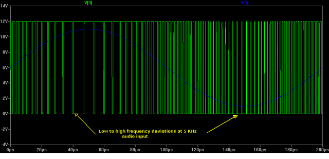
My first thought regarding the behavior of the circuit made me to think that this very wide stretching of bandwidth might jeopardize the sound quality of the music being played, but the truth is—it’s benign. In fact even no matter how large the frequency modulation is, when the output is being filtered the result is just always stays like the original. This is depicted in figure 7.
Figure 7. Modulation at 5 KHz with 5 volts amplitude shows how severe stretching of frequency from V max to V min of audio.
When I listen to the headphone with this kind of circuit configuration, I noticed there is a little mixture of crisp treble being reproduced compared to figure 1. Maybe this is the secret spice inherent to all self oscillating class d audio amp? Mixing of FM with PWM might produce useful harmonics that tend to make it more crisp in audio reproduction. Well, I have to investigate this a little bit further or maybe I am on the placebo effect only, LOL!
Unfortunately, I tested this circuit using only one channel due to no available 2 channel audio jack in my assorted box, (I’m still here in Norway) so full testing implementation with 2 channel is still on hold until I got that stuff. I think 200 KHz channel spacing is not enough (400 KHz would be adequate, (edited Aug. 8)) therefore, negative FB must be strictly implemented to reduce the severity of the FM modulation.
Thanks for looking,
Cheers
IQspice-4


Heh, i see you’re pursuing the class D route more… Me, i almost finished my 555-based power supply, tested working up to 200W with IRF740s (haven’t made the second 70v rail yet), and it works great.
Wonder what would come out if we combine my power supply with your amps and crossover. A sound system driven by 555s entirely! Wicked.
I cannot open your schematic on imageshack coz it is blocked by my ISP here on board the ship.. Is this 555 based power supply you’re referring to is the same circuit on imageshack? Care to show it to me via my email? Maybe it’s possible to tweak it a little to work as class d as well.
I’ll show you my schematic as soon as i get the final version done (didn’t bother updating the values as i worked on it).
I don’t think it can be used for class D audio because it does not use PWM. It uses pulse skipping (toggling the reset pin of the 555).
Well, I’m just joking.
Cheers
Love reading your articles. Helps me understand Class D. I know about FM and PWM from electronic music synthesis. Do you know of a Class D based on just one or two 555’s driving 200 watts or more? Cheers!