
This article is a follow up to my last post regarding class D amp using LM319 but some of you may feel less enthusiastic about LM319 due to its one channel approach using it’s one comparator, while the other remaining one was used as square wave/triangular generator. Well, this article will fill in the blank of the missing channels that can be implemented using single LM339 up to three or four channels at your own will.
I mentioned three channels if one comparator is used as oscillator but can be made four channels in a single chip if the oscillator will be provided externally by using LM555 timer.
Fig. 1 shows single chip 3 channel amplifier schematic circuit of LM339 using MOSFET driver TC4420 to drive speaker. The blue rectangular box encircling 6 TC4420 can be replaced by high side/low side FET drivers like IR2110 shown in Fig. 2
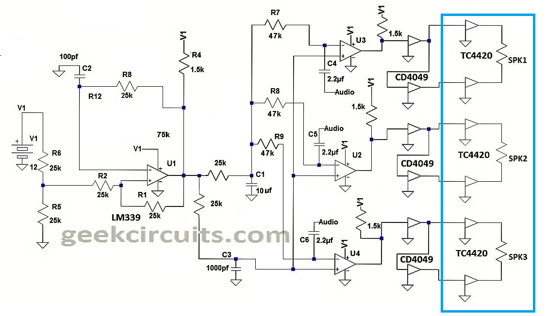
Fig. 1
Three channel LM339 plus 6 pieces TC4420 in full bridge topology.
Fig. 2 shows single chip 3 channel amplifier schematic circuit using LM339 with mosfet driver IR2110 and N channel power mosfets to drive speaker. CD4049 inverting CMOS were used to split the single ended output of LM339 into complementary form as required by IR2110 to drive the half bridge topology in the power output stage. R19, R20, R21, R22, R23 and R24 together with corresponding In4148 fast turn off diodes are added to avoid shoot through during switching transitions of power mosfets. This deadtime implementation is much desirable compared to doing it at the gate of the power mosfet for sharper knee response.
This circuit configuration is also called general purpose switching amplifier. Numerous application in industrial motor control such as application that pops up on the creative minds include a 3 phase inverter or VFD (variable frequency drive) that can be used to drive industrial induction motors if the inputs will be driven by a 3 phase variable frequency signal instead of audio source. Volume control must be implemented at the 3 inputs to increase or decrease the power and RPM of the motor. The 3 phase variable source can be made sinewave or square wave.
Although I have not yet made this circuit project in a working prototype due to the nature of my job as seaman in a passenger cruise ship 19 years ago, (yes, I made this circuit during my idle time onboard) surprisingly I almost forgot this project to implement until I came across it on my laptop. The circuit shown on the schematic below may need further scrutiny and must be evaluated via a breadboard before any attempt to be made into a final PCB prototype. These may include the deadtime adjustment of the diodes and resistors at the inputs of IR2110 which maybe too small or too large in resistance based on particular application just mentioned. These can increase deadtime causing distortion in audio amplifier applications but for VFD 3 phase inverter application, the greater the deadtime the better will be.
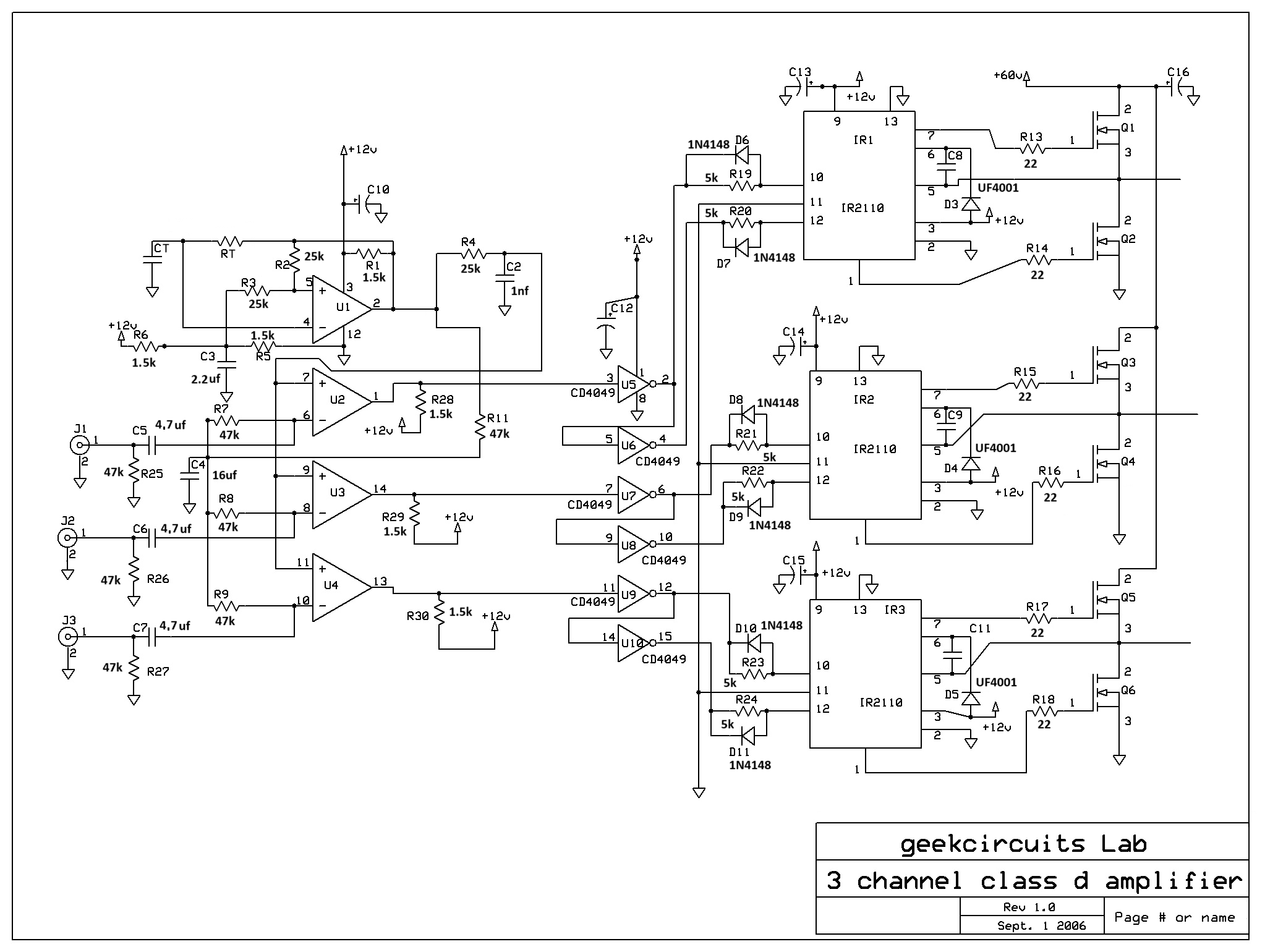
Fig. 3 shows the internal schematic circuit of LM339
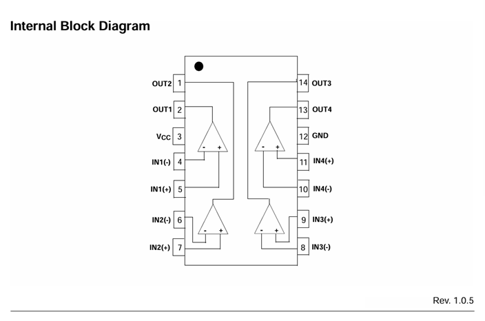
The